As a child, a hobby that a friend and I got into was R/C cars. This was an integral experience BECAUSE it led young me to learn about following detailed INSTRUCTIONS, assembling mechanical systems, basic electronic workings, as well as painting and detailing.
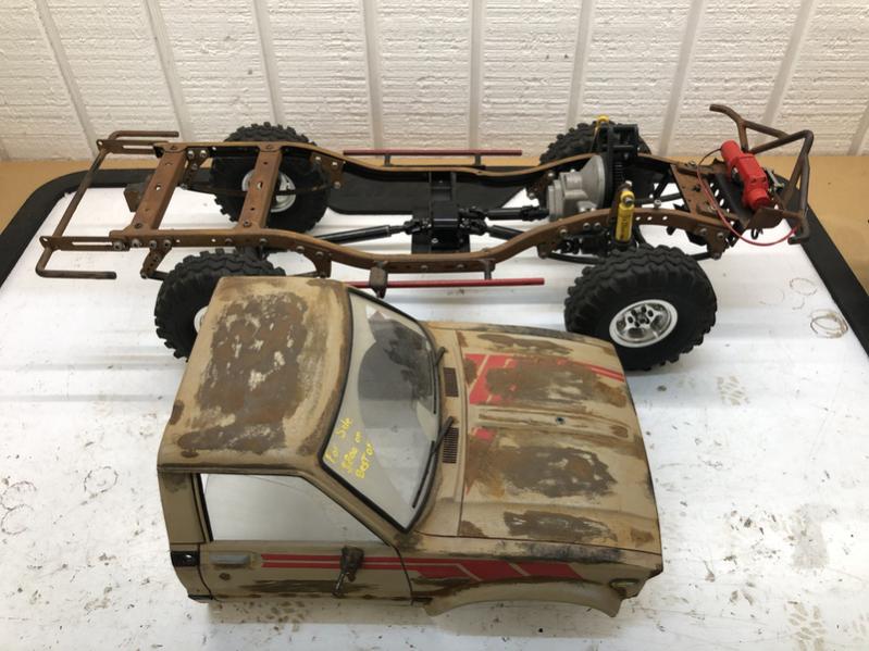
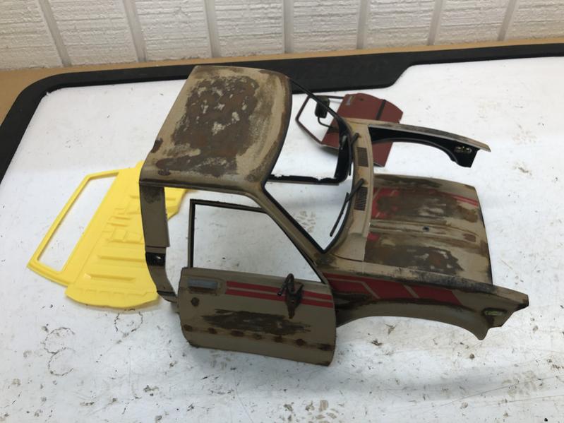
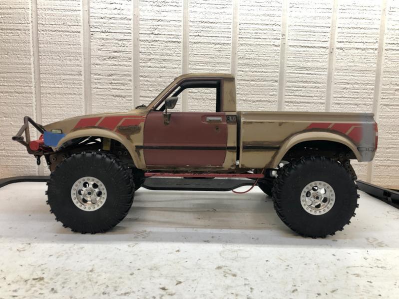
Years ago, I got interested in building a scale-accurate radio-controlled truck, partially from off the shelf parts and some fabrication as well. Here is what I started with…
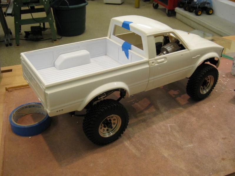
I started with a off the shelf Tamiya Hilux body. These (were at the time) readily AVAILABLE, but needed customization to be more realistic. A person in the hobby had a CNC machine and made a limited number of drop-bed kits made from thick styrene. From flat pieces, and using a chemical called MEK (basically a welder for plastic) the bed was made. The wheel wells are many little parts welded toghther and the corners rounded off.
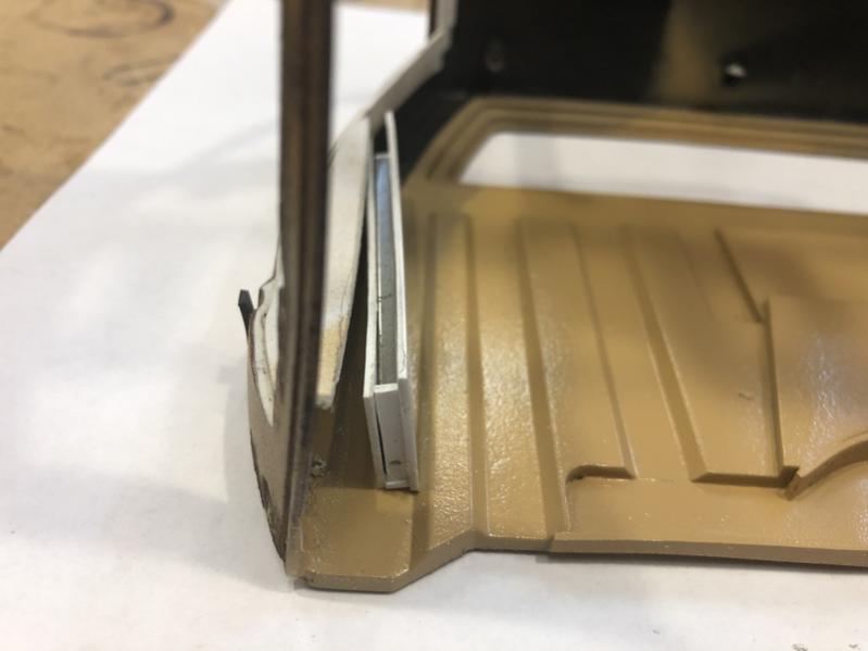
Next up was some detailing on the body. USing some heat and tools, I was able to create dents and scrapes. Also, layering paint helps with aging techniques.
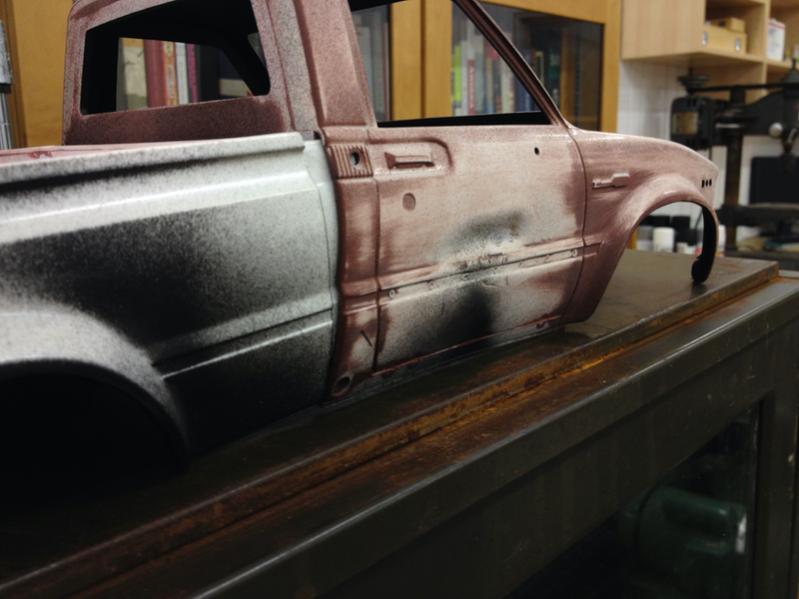
Here you can see how, when painted, how the underlying body modifications can come alive.
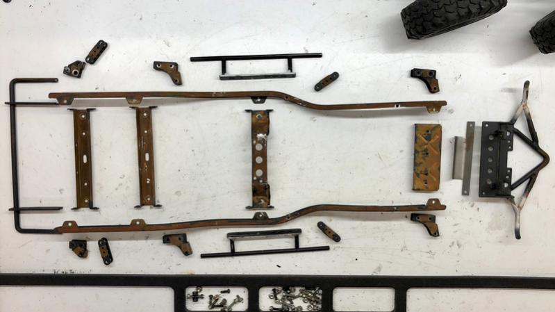
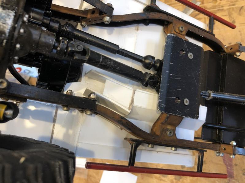
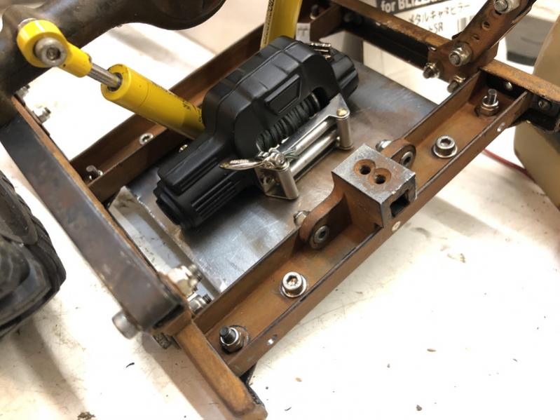
For a chassis, I sourced a vintage Tamiya Bruiser chassis (from 1986), which even to this day, is the most accurate one available. Normally silver, I used some weathering paitns and gave it an aged look.
The axles are units that were AVAILABLE from a company RC4WD which are no longer available. The housings were machined (not cast) from aluminum and the internals are high quality. It’s a shame that they moved away from making such quality bits in recent years. The leaf springs are ones that were sourced from a fellow HOBBYIST by the name of Chino63 who made his own custom military wrapped units and had them heat treated. It’s great when you can buy quality parts from fellow PASSIONATE hobby ENTHUSIAST.
The trasmission pictured above was an RC4WD unit which I was not pleased with and it was switched for an axial 3-gear unit. The wheels are true bead-lock units from GCM racing in Canada which are machined from aluminum, and are sadly no longer made. The red winch pictured is an old unit, again, from RC4WD which had very poor quality wires, so I DISASSEMBLED and soldered on quality wires and connectors.
I made a box out of some styrene platic sheets to hold the battery.
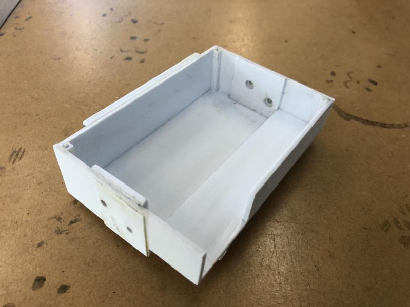
After painting it black, this lives behind the truck cab, and the bed acts as a battery box cover.
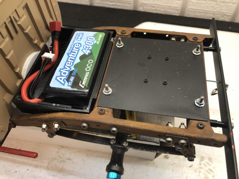
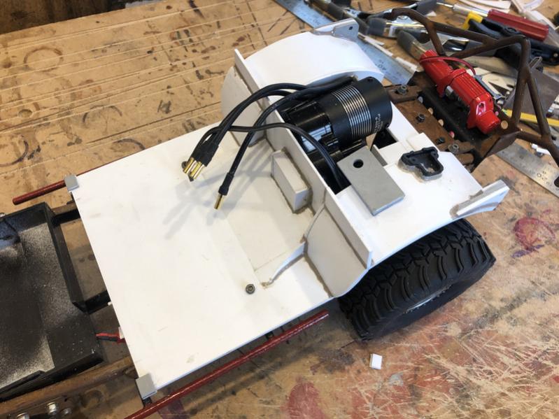
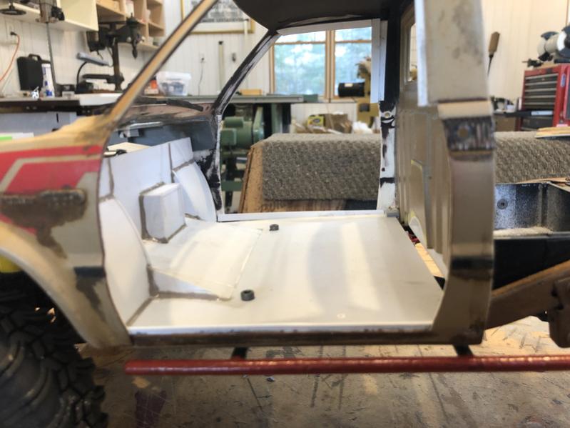
Next I made an interior tray, as well as inner fenders and space under the hood for the electronics to live.
To make the cab more REALISTIC, I cut the doors and hood off. THis is done, oddy enough, with sewing thread. This method works quite well and allows for one to cut any shape. I also installed a full cab back since I SEPARATED the bed from the cab.
Here is the cab mounted over the tray…
On the bottom of the tray i built a channel to run wiring thru.
For proper accuracy, I needed to make some door-jams. I sneakily hid rare-earth MAGNETS in them to keep the doors closed, but could open then as needed.
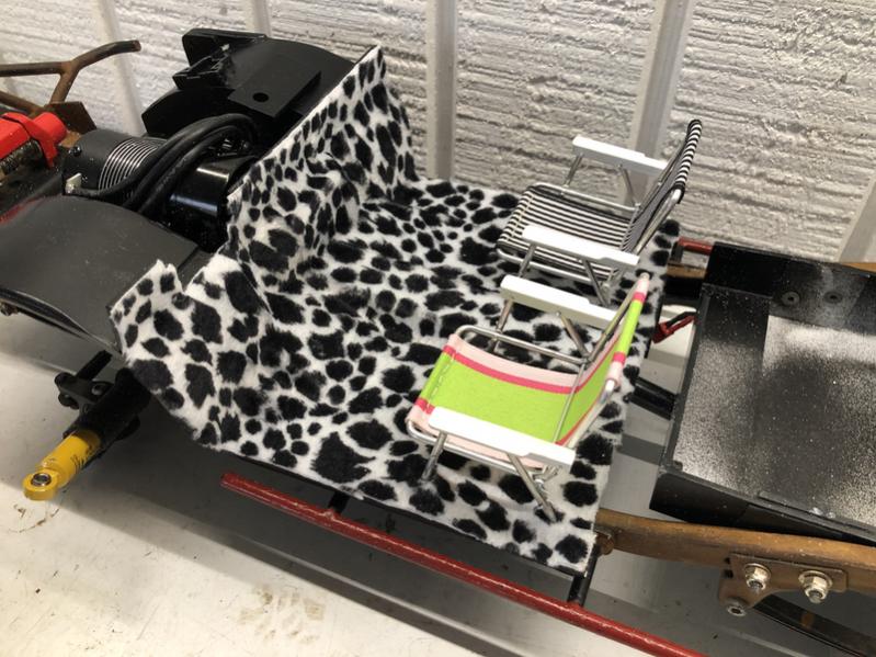
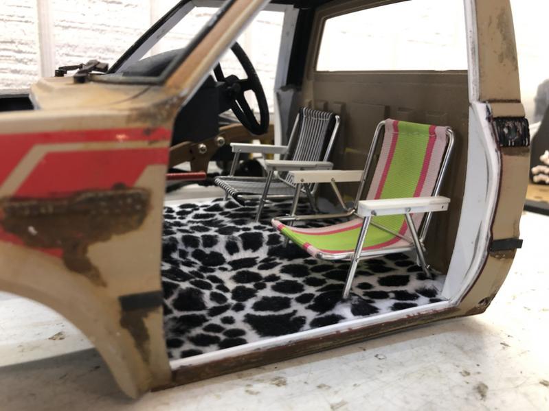
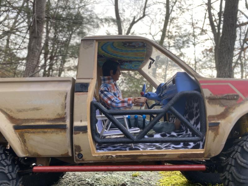
I installed some of the finest cow-print rugs offered. I also had some lawn chairs that were a kit that a fellow HOBBYIST offered many years ago. They were DIFFICULT to make, and I basically had to create 50% of them from scratch. They brought smoe humor to the project.
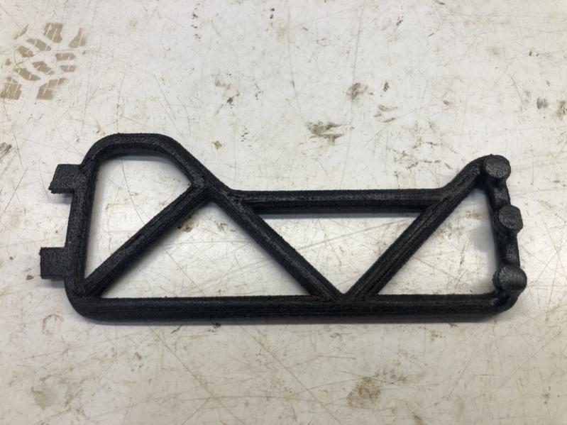
A friend 3-d printed some tube doors. This, along with the hidden magnets, allows me to open and close the doors. Also, I can use either the tube doors for an open air look, or the full door. You can see where I glued 3 small rare earth magnets on each tube door.
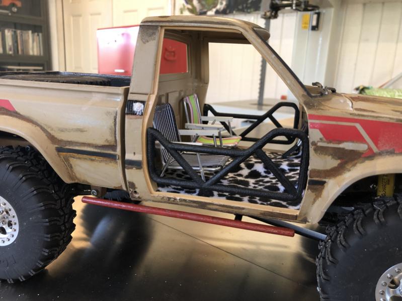
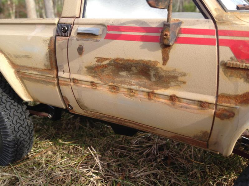
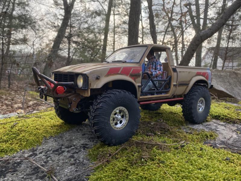
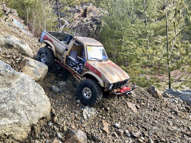
Here is the truck with the full doors. I also decided to ‘bob’ (shorten) the bed. If you look closely, I applied a very thin strip of styrene over the cut line, and while it was wet with MEK welder, I pressed my exacto knife into it to make it look like a weld line.
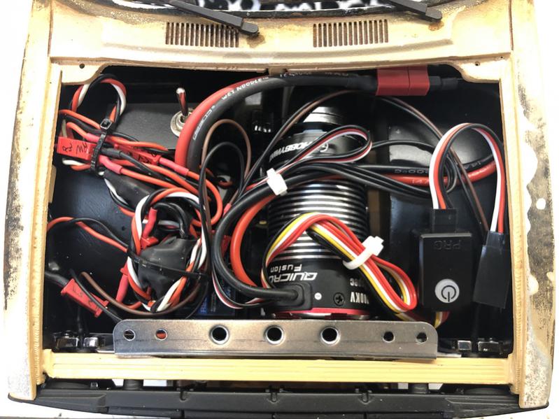
The electronics on this could be a post on it’s own, but i’ll attempt break it down to make it simple: I love soldering and wiring. Many people hate wiring but SOMETHING about it I really enjoy. I decided to make as much as POSSIBLE from scratch, as the quality of wires, LED’s and CONNECTORS are usually fairly poor from off the shelf parts.
I used a combination motor and speed controller in one unit to save space. The steering servo is a high quality low-profile unit from holmes hobbies which draws power directly from the battery. I use a very old Futaba 4PL transmitter that uses micro receivers that have no antenna.
As for the rest, I used silicone wire for all the led lighting, and winch controlling. I also used micro-deans connectors for all the connections. For the battery connectors, I used a high guage wire and (normal) deans connectors. For LED lighting, I found some warm-white diodes for the headlights, and some good quality red diodes for the tail lights. I find pre-made lighting set-ups never fit right, the bulbs are usually too ‘cool’ to look correct for an old model vehicle, and they many times cannot handle the higher voltages used in these models.
My transmitter is a 4-channel unit (again, it’s very old). I required 5 channels, so I installed a toggle switch for the front and rear winches. I just have to open the hood and toggle the switch and the single winch controller will activate either the front or rear winch. A simple solution.
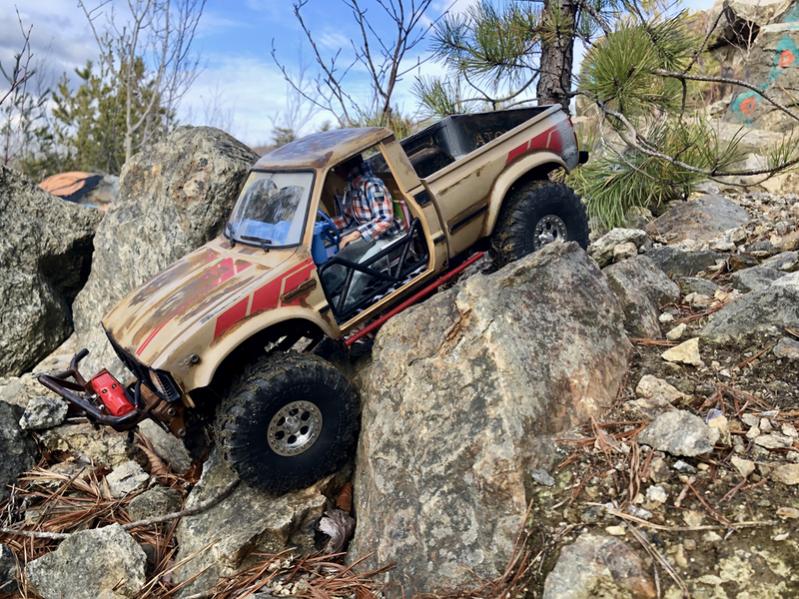
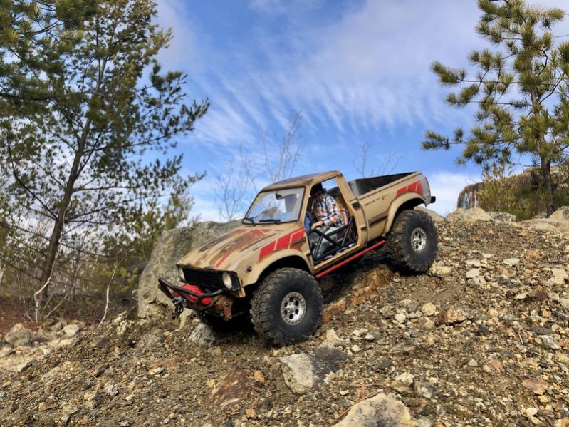
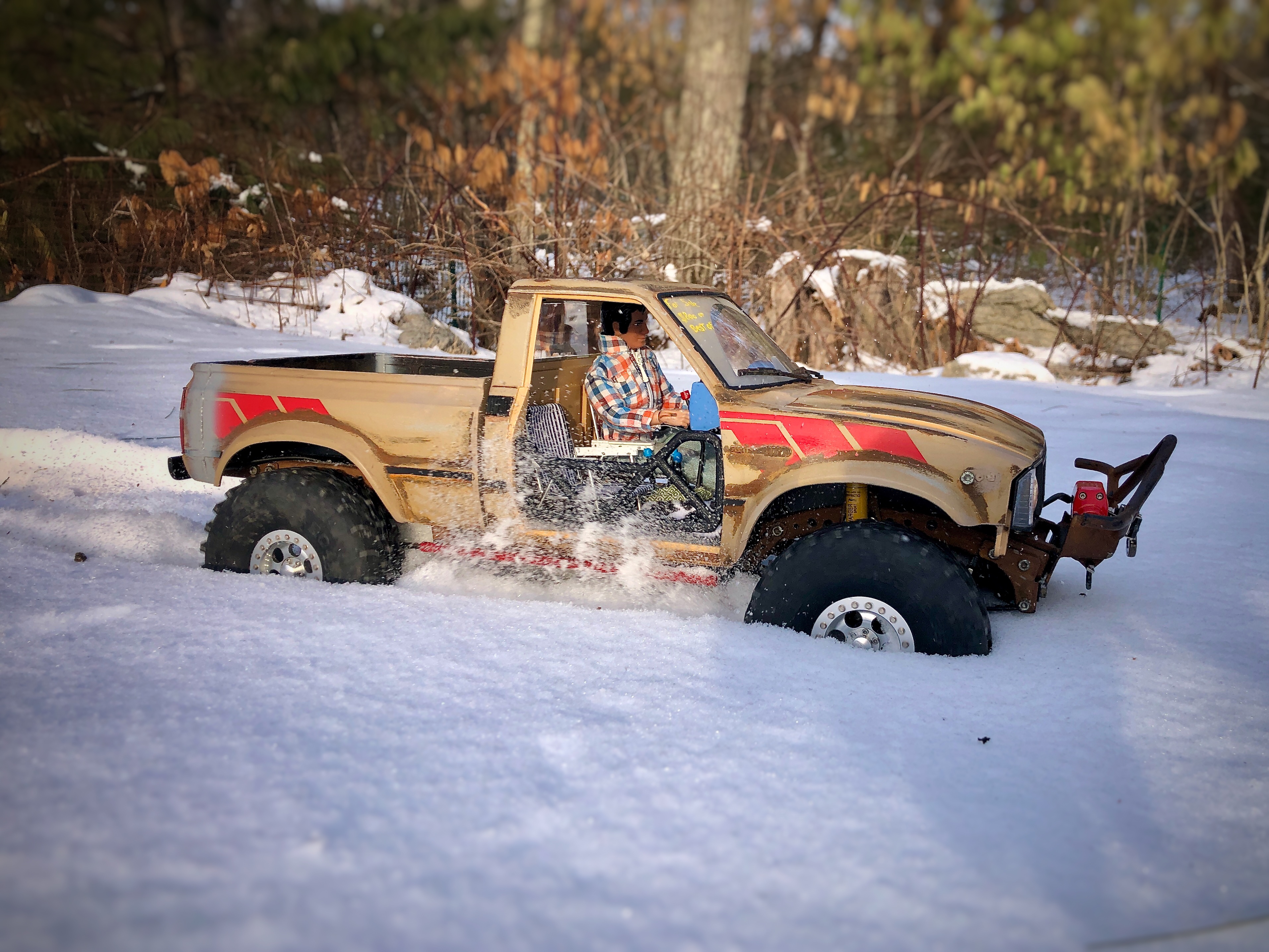
I installed a 1:9 driver figure, which are very hard to find in this scale. Here are some shots of the truck outside, in it’s finished state…
In this project I used welding, painting, plastic construction, electronics, mechanical skills, and most of all patience. These little R/C’s are a very rewarding way to exercise many skills if one is willing to gather random parts and attempt to make them all work TOGETHER.
This was a very CONDENSED version of this project that I DOCUMENTED in much greater detail over at the scale builders guild forum. If you have a visit over there, have a look at the dates which can give you an idea of how long something like this can actually take.
thanks for being here…

Leave a comment